Oscilloscope Based Software
I3C Electrical Validation Software
Model No: PGY-I3C-EV
I3C Electrical Validation Software offers electrical measurements compliance testing as specified in the I3C specification. PGY-I3C-EV Electrical validation software runs in Tektronix Oscilloscope and provides electrical measurements at the click of a button. This allows engineers quickly check for I3C compliance and flexibility to debug the failure. In addition to this engineers can decode the command and response of I3C to debug the communication. PGY-I3C-EV takes advantage of digital channels of MSO and provides the decoding of I3C data lines.
- I3C
 Free Online Technical Support
 Free Software Updates
 Global Sales Support
 Evaluation Units Available
- Key Features
- Specifications
- Supports electrical measurement for Fast, Fast plus, Push-Pull and Open Drain with limit comparison.
- Links the content to the electrical signal in the oscilloscope for easy understanding of the electrical characteristics of the protocol.
- Zooms the selected I3C packet content in the decode table in the waveform plot waveform window for easy analysis of electrical characteristics of the I3C frame.
- Detail view correlates physical layer waveform with I3C packet data.
- Utility features like zoom, undo, and fit screen for easy debugging while correlating the electrical data to the waveform.
- Ability to store the I3C electrical data in CSV and txt format.
- Report Generation
- Supports WFM file format for offline analysis
Now design and test engineers can automatically make accurate and reliable electrical measurements and decode protocols in PGY-I3C-EV software using data acquired by Tektronix DPO5000, TDS7000, DPO/DSA/MSO7000, MSO5/6 series oscilloscope to reduce the development and test cycle.
Seamless Integration with Oscilloscope
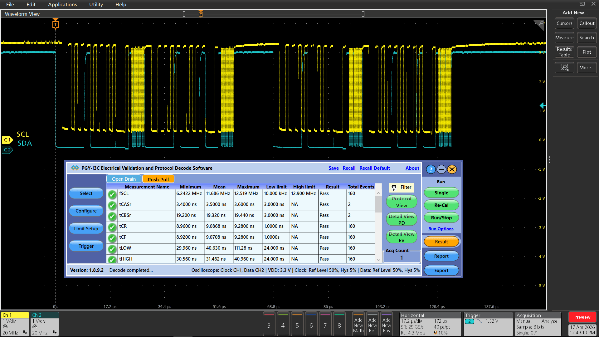
PGY-I3C-EV runs inside the Tektronix oscilloscopes and makes the electrical measurements, and displays the decoded data in a bus diagram, a table, and links the decoded data to electrical signal in the bus diagram.

Reference Level Setup
PGY-I3C-EV is not just for standard electrical compliance testing, you can also vary the limits and test your device with custom limits. The intuitive limits and reference level setup allow you to configure the limits and reference levels for your custom testing needs. This enables you to test your device beyond the specification and characterize it.

Powerful Debug Environment:
Debug Window
PGY-I3C-EV Software provides two types of debugging capabilities. In one of them, the worst-case result can be selected and linked directly to the waveform as shown here. The software provides the flexibility to define the number of acquisitions and the results will include worst-case results for all these acquisitions. The software can link the worst-case results to corresponding waveform acquisition using a simple right click of a mouse.

I3C Timing Requirements When Communicating With I2C Legacy Device
| S.No | Electrical Parameter | Symbol |
|---|---|---|
| 1 | SCL(High-speed serial clock) Clock Frequency | fSCL |
| 2 | SCL Clock Low Period | tLOW |
| 3 | SCL Clock High Period | tHIGH |
| 4 | SCL Signal Rise Time | trCL |
| 5 | SCL Signal Fall Time | tfCL |
| 6 | Pulse Width of Spikes that the Spike Filter Must Suppress | tSPIKE |
| 7 | Bus Free Time Between a STOP Condition and a START Condition | tBUF |
| 8 | SDA Signal Rise Time | trDA |
| 9 | SDA Signal Fall Time | tfDA |
| 10 | Data Setup Time | tSU,DAT |
| 11 | Data Hold Time | tHD,DAT |
| 12 | Setup Time for a Repeated START | tSU,STA |
| 13 | Hold Time for a Repeated START | tHD,STA |
| 14 | Setup Time for STOP | tSU,STO |
I3C Open Drain Timing Parameters
| S.No | Electrical Parameter | Symbol |
|---|---|---|
| 1 | Fall time of SDA Signal | tfDA_OD |
| 2 | Low Period of SCL Clock | tLOW_OD |
| 3 | SDA Signal Rise Time | trDA_OD |
| 4 | High Period of SCL Clock | tHIGH |
| 5 | Data Hold on SDA Signal in Open Drain Mode | tHD_OD |
| 6 | Data Setup on SDA Signal in Open Drain Mode | tSU_OD |
| 7 | SCL Signal Rise Time | tr |
| 8 | SCL Signal Fall Time | tf |
| 9 | Bus Available Condition | tAVAL |
| 10 | Bus Idle Condition | tidle |
| 11 | Clock After Start Condition | tCAS |
| 12 | Clock Before Start Condition | tCBP |
| 13 | Current Master to Secondary Master Overlap time during handoff | tMMOverlap |
| 14 | Time Interval where new Master Not Driving SDA Low | tMMLock |
I3C Push-Pull Timing Parameters for SDR and HDR-DDR Modes
| S.No | Electrical Parameter | Symbol |
|---|---|---|
| 1 | SCL Clock Frequency | tFDA_OD |
| 2 | SCL Clock Low Period | tLOW_OD |
| 3 | SCL Clock High Period | tRDA_OD |
| 4 | SCL Clock Rise Time | tHIGH |
| 5 | SCL Clock Fall Time | tHD_OD |
| 6 | SDA Signal Data Hold in Push-Pull Mode | tSU_OD |
| 7 | SDA Signal Data Setup in Push-Pull Mode | tCR |
| 8 | Clock After Repeated START (Sr) Condition | tCF |
| 9 | Clock Before Repeated START (Sr) Condition | tAVAL |
| 10 | Clock in to Data Out for Slave | tIDLE |
| 11 | SDA Signal Fall Time | tCAS |
| 12 | SDA Signal Rise Time | tCBP |
Detail View
")
In Detail View, engineers can view the analog waveform and details of electrical measurements in a single view. If there is any failure in electrical measurement, designers can quickly correlate with the analog waveforms. Users can select any row in the detail view; corresponding analog waveforms will be zoomed in and displayed. In the same row, engineers can view all the electrical measurements corresponding to the selected row. Utility features such as Zoom, cursors, and markers make custom measurements while debugging.
Similar Products
-
 Protocol Exercisers & Analyzers
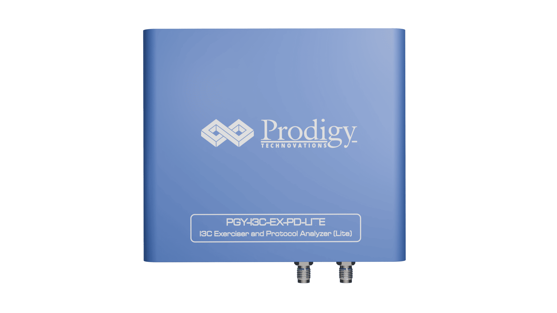
I3C Protocol Exerciser and Analyzer – Lite
The PGY-I3C Lite is a Protocol Analyzer…
-
 Protocol Exercisers & Analyzers
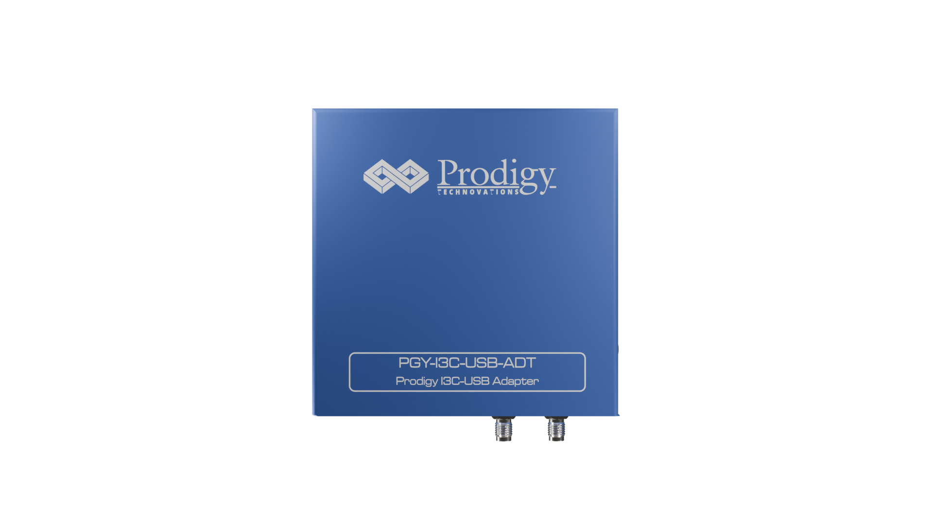
I3C USB Adapter
The PGY-I3C_USB_Adapter provides the ability to operate…
-
 Oscilloscope Based Software
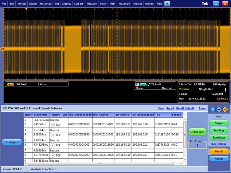
10BaseT1S Protocol Decode Software
10BaseT1 is emerging as a key interface…